vSRXを2台使用して、HAであるシャーシクラスタ構成を構築するメモ
環境
- ESXi7.0 Update 3
- Juniper vSRX3.0 : 20.4R3.8
構成図
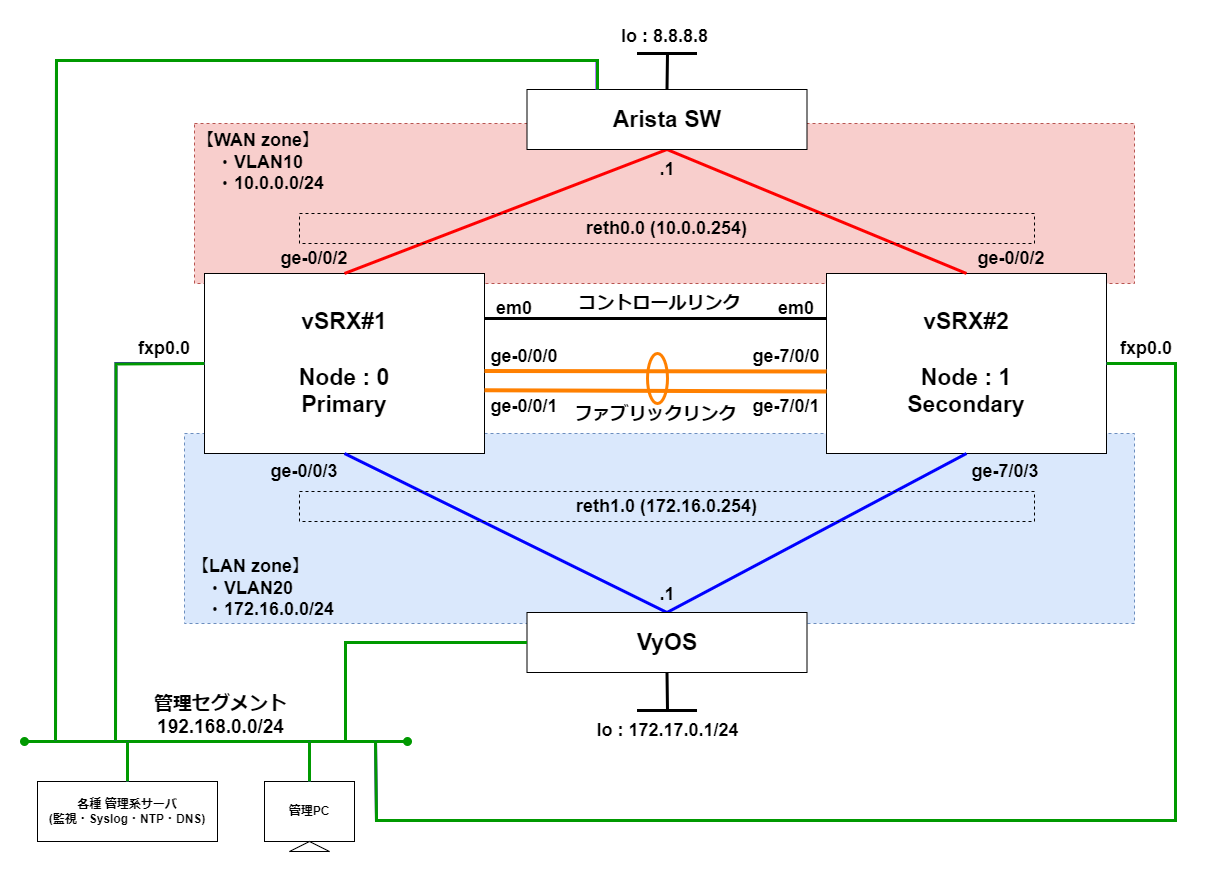
下記の構成図のvSRX#1とvSRX#2を構築していく。
前提
- 2台vSRXが用意されていること
- 未構築の場合、以下URLを参考にして構築してください。

ネットワークアダプタとインターフェースの関係について
vSRXではネットワークアダプタを追加する際に、必ずアダプタ タイプを「VMXNET3」にしましょう。うまく作成されなかったり、シャーシクラスタが一生組めなくなります。
シャーシクラスタ設定後、ネットワークアダプタとインターフェース名の関係性は以下のようになる。
| ネットワークアダプタ | インターフェース名 |
|---|---|
| 1 | fxp0 |
| 2 | em0 |
| n(3以上) | ge-0/0/n-3(node0)、ge-7/0/n-3(node1) |
シャーシクラスタ構成後は、自動的にコントロールリンクが「em0」になります。
ファブリックリンクは任意に最大2つまで設定することが可能です。
手順
Chassis Cluster設定を有効化
root@:~ # cli
root> configure

# 設定の全削除
root# delete
This will delete the entire configuration
Delete everything under this level? [yes,no](no) yes を入力

# 1/2号機でrootパスワード設定
root# set system root-authentication plain-text-password
New password: ********
Retype new password: ********
root# commit and-quit

# Chassis Cluster設定を有効化
## 1号機で実施
root> set chassis cluster cluster-id 1 node 0 reboot
## 2号機で実施
root> set chassis cluster cluster-id 1 node 1 reboot
※以下からのCLI設定はすべて1号機のみで実施する
SSH設定+機器固有設定(管理用インターフェース)
SSHできるようにする
root# set groups node0 interfaces fxp0 unit 0 family inet address 192.168.0.10/24
root# set groups node1 interfaces fxp0 unit 0 family inet address 192.168.0.11/24
root# set apply-groups ”${node}”
root# set system services ssh root-login allow
root# commit and-quit
root> exit
※以下から1号機へのSSHから設定をするとコピペやログ取得ができるようになり楽になります。
インターフェースの追加
インターフェースを追加するために、まずパワーオフにします。
root> request system power-off
Power Off the system ? [yes,no] (no) yes を入力
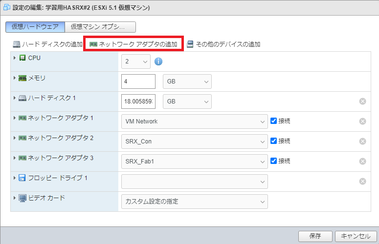
[ネットワークアダプタの追加]を押下。
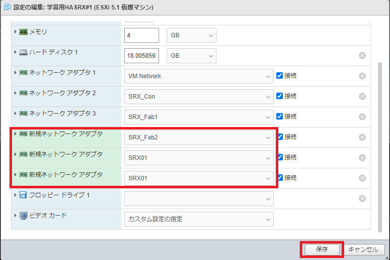
追加した、ネットワークアダプタを「VMXNET3」に変更。
使用するインターフェースを全部追加作成をして、[保存]を押下。
再度起動をさせて下さい。
機器固有設定(ホスト名)
root# set groups node0 system host-name vSRX01
root# set groups node1 system host-name vSRX02
Fabricリンク設定
root@vSRX01# set interfaces fab0 fabric-options member-interfaces ge-0/0/0
root@vSRX01# set interfaces fab0 fabric-options member-interfaces ge-0/0/1
root@vSRX01# set interfaces fab1 fabric-options member-interfaces ge-7/0/0
root@vSRX01# set interfaces fab1 fabric-options member-interfaces ge-7/0/1
redundancyグループ設定
redundancy-group(以下RG)0はルーティングエンジン用(=コントロールリンク、ge-0/0/0)に使用される。
Active/Standby構成時はRG1のみを使用して、パケットフォワーディング用(=ファブリックリンク、reth(Redundant Ethernet Interface))に使用される。
Active/Active構成時はRG1以上を使用する。
今回はActive/Standby構成のため、RG0とRG1の設定を行う。
RG0・RG1ともに、node1(1号機)をPrimaryにするため、priorityを高く設定する。
root@vSRX01# set chassis cluster redundancy-group 0 node 0 priority 100
root@vSRX01# set chassis cluster redundancy-group 0 node 1 priority 1
root@vSRX01# set chassis cluster redundancy-group 1 node 0 priority 100
root@vSRX01# set chassis cluster redundancy-group 1 node 1 priority 1
interfaceモニタリング設定
interfaceモニタリングのメンバーに設定したインターフェースで障害が発生したとき、RG1(データプレーン用)のフェールオーバーが発生する。
root@vSRX01# set chassis cluster redundancy-group 1 interface-monitor ge-0/0/2 weight 255
root@vSRX01# set chassis cluster redundancy-group 1 interface-monitor ge-0/0/3 weight 255
root@vSRX01# set chassis cluster redundancy-group 1 interface-monitor ge-7/0/2 weight 255
root@vSRX01# set chassis cluster redundancy-group 1 interface-monitor ge-7/0/3 weight 255
冗長インタフェース設定
冗長インターフェース(以下reth)は要するに、仮想IP(VIP)のような設定である。
rethにIPを設定して、このrethを対象の物理インターフェースに対応づけることができる。
root@vSRX01# set chassis cluster reth-count 2
root@vSRX01# set interfaces reth0 redundant-ether-options redundancy-group 1
root@vSRX01# set interfaces reth0 unit 0 family inet address 192.168.2.1/24
root@vSRX01# set interfaces reth1 redundant-ether-options redundancy-group 1
root@vSRX01# set interfaces reth1 unit 0 family inet address 172.16.0.1/24
もし、VLANタグを設定する場合は、以下設定も追加する。
root@vSRX01# set interfaces reth0 vlan-tagging
root@vSRX01# set interfaces reth0 unit 0 vlan-id 10
root@vSRX01# set interfaces reth1 vlan-tagging
root@vSRX01# set interfaces reth1 unit 0 vlan-id 20
冗長インターフェースを物理インターフェースに割り当て
冗長インターフェースであるrethに物理インターフェースを設定していく。
冗長インターフェースと物理インターフェースの組み合わせは以下である
- reth0:「ge-0/0/2」と「ge-7/0/2」
- reth1:「ge-0/0/3」と「ge-7/0/3」
root@vSRX01# set interfaces ge-0/0/2 gigether-options redundant-parent reth0
root@vSRX01# set interfaces ge-7/0/2 gigether-options redundant-parent reth0
root@vSRX01# set interfaces ge-0/0/3 gigether-options redundant-parent reth1
root@vSRX01# set interfaces ge-7/0/3 gigether-options redundant-parent reth1
セキュリティゾーン設定
セキュリティーゾーンとして「WAN」と「LAN」を作成する。
root@vSRX01# set security zones security-zone WAN interfaces reth0.0
root@vSRX01# set security zones security-zone LAN interfaces reth1.0
commit
設定保存をする。
root@vSRX01# commit and-quit
node0:
configuration check succeeds
node1:
commit complete
node0:
commit complete
Exiting configuration mode
確認コマンド
-
show chassis cluster status
シャーシクラスタの状態を確認することが可能root@vSRX01> show chassis cluster status Monitor Failure codes: CS Cold Sync monitoring FL Fabric Connection monitoring GR GRES monitoring HW Hardware monitoring IF Interface monitoring IP IP monitoring LB Loopback monitoring MB Mbuf monitoring NH Nexthop monitoring NP NPC monitoring SP SPU monitoring SM Schedule monitoring CF Config Sync monitoring RE Relinquish monitoring IS IRQ storm Cluster ID: 1 Node Priority Status Preempt Manual Monitor-failures Redundancy group: 0 , Failover count: 1 node0 100 primary no no None node1 1 secondary no no None Redundancy group: 1 , Failover count: 1 node0 100 primary no no None node1 1 secondary no no None -
show chassis cluster interfaces
シャーシクラスタに設定しているモニターインターフェース等のインターフェース情報を確認可能。root@vSRX01> show chassis cluster interfaces Control link status: Up Control interfaces: Index Interface Monitored-Status Internal-SA Security 0 em0 Up Disabled Disabled Fabric link status: Up Fabric interfaces: Name Child-interface Status Security (Physical/Monitored) fab0 ge-0/0/0 Up / Up Disabled fab0 ge-0/0/1 Up / Up Disabled fab1 ge-7/0/0 Up / Up Disabled fab1 ge-7/0/1 Up / Up Disabled Redundant-ethernet Information: Name Status Redundancy-group reth0 Up 1 reth1 Up 1 Redundant-pseudo-interface Information: Name Status Redundancy-group lo0 Up 0 Interface Monitoring: Interface Weight Status Redundancy-group (Physical/Monitored) ge-7/0/3 255 Up / Up 1 ge-7/0/2 255 Up / Up 1 ge-0/0/3 255 Up / Up 1 ge-0/0/2 255 Up / Up 1


